 Aug 24, 2026

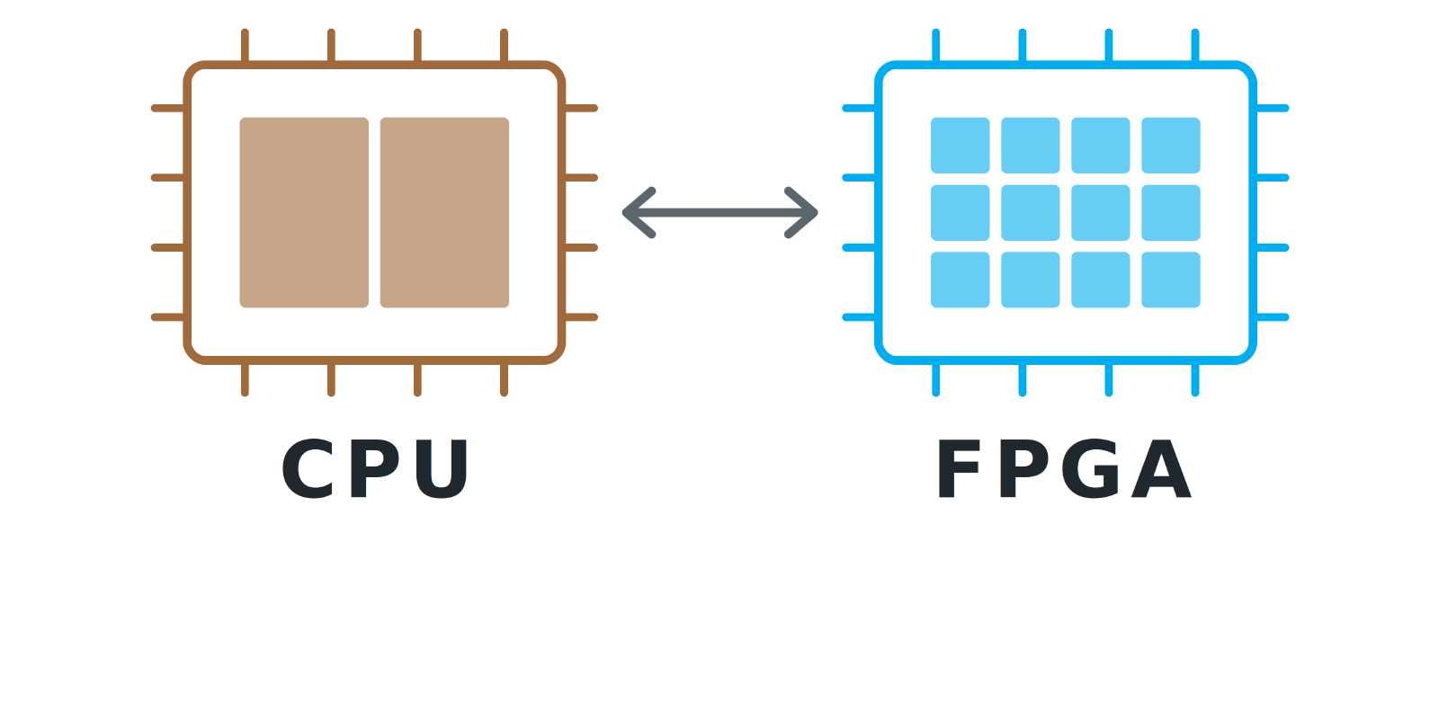
You have a microcontroller board (e.g. my RPi Pico) that is working fine but now, I found out that the system is too slow to meet performance requirements. One option is to go to a beefier microcontroller but that does not help with latency variance. At one point, it is not possible or realistic to use that upscaling. That is where FPGA comes into play. It can be used to prepare the inputs for the microcontroller and therefore remove calculations.
What is an FPGA
An FPGA is a programmable chip that can be used next to a microcontroller. Its main difference is that, contrary to the microcontroller, it does not operate sequentially but in a parallel way. All the elements create a set of logic functions that the user can configure at will. It can be used to accelerate computations (such as digital signal processing, cryptography, etc) or get accurate timing for a set of operations (a PID controller on a process that needs to meet very accurate timings). It is programmed using Hardware Description Languages (such as VHDL or SystemVerilog), High Level Synthesis (using a small subset of C/C++, don’t expect to port your existing programs there directly).
Datapath Acceleration Example
I have a digital signal processing pipeline in an MCU but for some reason, the microcontroller cannot keep up with the load when I increase the bandwidth.
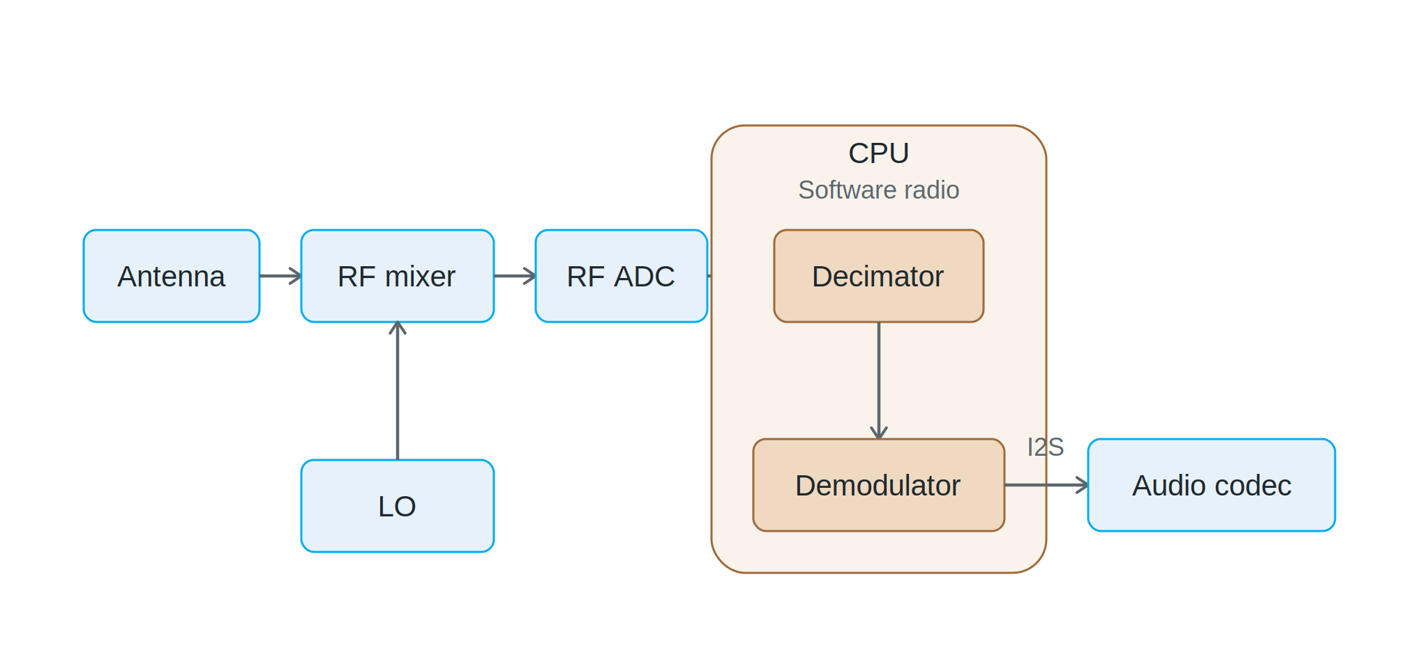 One way is to accelerate parts of the processing to ensure that the flexibility is kept in the software side.
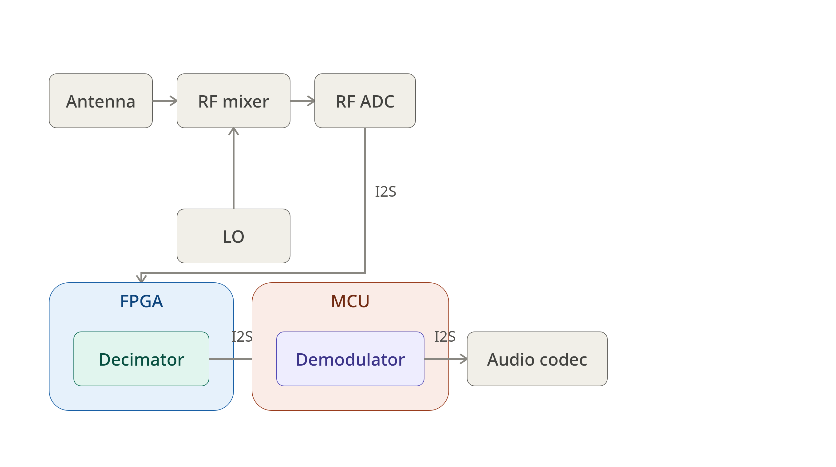 Inserting the FPGA in the signal path allows the MCU to work with a reduced sample rate and therefore a reduced load.
Bus possibilities for acceleration
I2C, I3C, SPI, UART
Those four basic buses are the foundation of the communication between a microcontroller and an FPGA. They are relatively slow and easy to deploy.
- I2C/I3C is a two wire bus protocol that can connect multiple parts together. Typical speed is 400 kHz for I2C and 12.5 MHz for I3C. Those buses are typically used to configure control registers.
- SPI is a 4-lines synchronous bus that acts as a shift register. SPI can be made faster by using dual/quad/octal mode at the same clock speed which transfers multiple bits in parallel.
- UART is an asynchronous full-duplex protocol that consists of data exchanged between two parties at a defined speed.
All those buses are easily implemented in FPGA. The FPGA designer and software developper agree on a protocol to use to exchange data between MCU and FPGA over SPI, I2C/I3C, or UART.
I2S
I2S is the standard data transfer format for audio, and it can also be used to transfer I/Q data. The I2S clock on a typical microcontroller is around 6.144 MHz (to transfer 2x16 bits at 192 kHz).
Conclusion
Adding an FPGA next to a microcontroller is not a replacement for the MCU. It is only meant to offload the tasks that the MCU cannot keep up with whether it is raw computation, sample-rate reduction, or timing that must stay deterministic no matter what. Once the preprocessing is done in the FPGA, the choice of bus (I2C, SPI, UART) becomes a question of what data must reach the MCU and how fast.
For most low-to-mid bandwidth projects, a simple SPI or I2C link is enough to get most of the benefits of the FPGA acceleration while not requiring a full software architecture change.